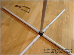
Ich wollte schon länger eine Magloop selber bauen, da ich von der Idee fasziniert war, mit einer kleinen Antenne aus meiner Wohnung heraus QRV zu sein. Außerdem waren mir die kommerziellen Lösungen einfach zu teuer. Für eine günstige Antenne ist man schnell 400-500 Euro los. Mechanisch etwas stabilere für den Dauereinsatz draußen kosten schnell über 1.000 Euro. Nachdem ich ein wenig gegoogelt hatte und einige Funkerkollegen zu dem Thema interviewt hatte, habe ich mich dafür entschieden einfach eine "Quick & Dirty" Magloop hinzuzimmern, um dann am Netzwerkanalysator zu schauen was passiert. Dazu bin ich am Wochenende mit Peter, DC2ZO in den Baumarkt und wir haben uns für je 12 Euro die Bauteile gekauft, um die Antenne schon mal hinzustellen. Die Kreuzverbinder gab es nicht bei den Elektro-Installationsrohren. Wir mussten ganz schön suchen, bis wir bei Treppen / Geländern passende Verbinder gefunden hatten.
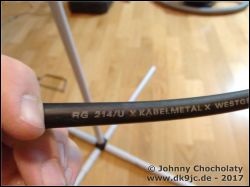
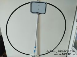
Als Kabel verwende ich ein altes Stück RG-214 mit doppeltem Schirm, welches ich auf 3m abgeschnitten habe. Das ergibt genau einen Meter Durchmesser.
Zuerst betrieb ich die Loop auf 20m (14.076 MHz) und 30m (10.138 MHz) mit einem "festen" Kondensator aus einem Stück RG-58 Koaxkabel. Ich erreiche so ein SWR besser als 1,6 und tune dann mit dem internen Tuner des TRX.
Mit einem 1m langen Koaxkabel als Kondensator (RG-58 hat ca. 101 pF pro Meter) hatte die Antenne ein SWR von 1:11, durch millimeterweises Kürzen des Kabels kam ich nell in den Bereich von 2,2.
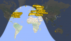
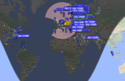
In der Betriebsart JT65 hatte ich mit der Antenne schon Verbindungen in die USA, Schweden und Litauen. Gehört wurde ich aber auch in Kanada, Brasilien und Japan.
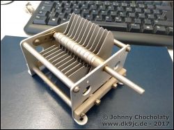
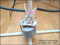
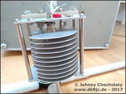
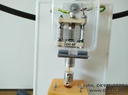
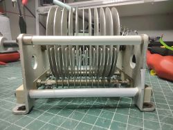
Bei Ebay habe ich dann einen Drehkondensator ersteigert. Dieser Drehko hat 15pf – 150pf und 2,5mm Plattenabstand. Da ich nur 5W und in Ausnahmen maximal 10W mache sollte es keine Probleme geben. Der Drehko würde sicher auch 50-100W an der Loop locker verkraften.
| 10m | 19 pF |
| 12m | 25 pF |
| 15m | 34 pF |
| 17m | 47 pF |
| 20m | 77 pF |
| 30m | 149 pF |
| 40m | 305 pF |
| 60m | 533 pF |
| 80m | 1.196 pF |
Mein ersteigerter Drehko sollte also theoretisch von 10m - 30m funktionieren. In der Praxis war jedoch 17 - 40m in Ordnung. Da sieht man, dass die Rechner nur eine grobe Orientierung sind.
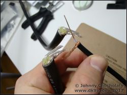
Ich habe den Drehkondensator fix anstelle des Koaxkondensators eingesetzt. Dazu wird einfach ein Ende des Koaxkabels (Schirm, ggf. mit Innenleiter) an eine Seite des Kondensators und das andere Ende des Koaxkabels an das andere Ende des Kondensators montiert. Auf dem Bild verwende ich testweise einfach Lüsterklemmen.
Mit dem Netzwerkanalysator habe ich auf 17m abgestimmt und dann direkt ZS1ALJ in Südarika gearbeitet. Erstaunlicherweise kam ich sogar auf 30m direkt zu R1AY in Russland durch. Ich habe trotz einem Wirkungsgrad von 15% und -9 db Gewinn noch einen Rapport von -02 bekommen.
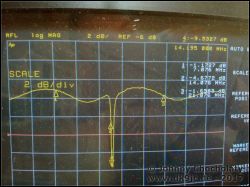
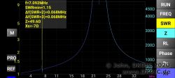
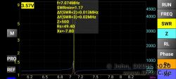
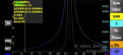
In den Fotos (Netzwerkanalyser) sieht man übrigens schön die Charakteristik einer Magloop. Abstimmen ist nicht ganz so einfach, da die Kurve sehr spitz ist. 1mm Drehung entscheiden schon zwischen einem unendlichen SWR und 1:1.
Fazit
Eine Magloop zu bauen ist leichter als man denkt. Ich habe ca. 2-3 Stunden inkl. Messungen für den Aufbau gebraucht. Wenn man die Antenne ordentlich abstimmt, arbeitet die Antenne wirklich verblüffend. Eine richtige Wunderantenne. Das hätte ich so nicht erwartet. Gerechnet habe ich übrigens nicht. Unter 66pacific.com gibt es einen tollen Loop-Rechner. Vergesst nicht, ihn vorher auf metrisch zu stellen.
Update 16.12.2018:
Ich habe auf 17m VP8LP in Stanley, Falkland Inseln, 12.787 km gearbeitet: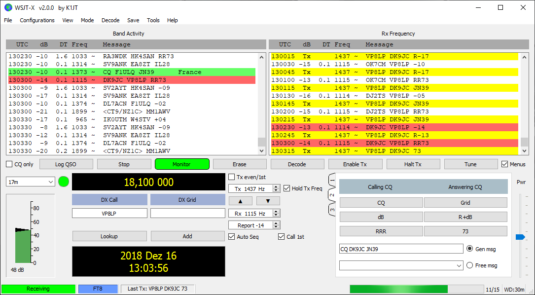
Update 24.12.2018:
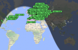
Ich habe weitere 3m RG-214 genommen und diese mit dem anderen verlängert und dann in 2 Windungen aufgerollt. So komme ich nun auf eine (doppelte) Loop mit 6m Gesamtumfang. Diese Loop ließ sich direkt auf 60m abstimmen. Ich konnte Nachmittags die ganze EU in FT-8 damit arbeiten. Ich habe dann später einen Schalter eingebaut um 2 WIMA FKP-1 150pF Kondensatoren in Serie (75pF gesamt bei doppelter Spannungsfestigkeit) parallel zum Dehrko zu schalten. Abstimmen auf 80m klappte auch sofort. QSOs waren direkt innerhalb Deutschlands möglich. Nachts ging sogar EU.
I get many questions from international readers, so I will continue in English from now on here, too.
Update 21.01.2019:
Magloop aus 26" Zoll Fahrradfelge gebaut (Mag Loop Magnetic Loop DIY with trashed 26 inch bicycle rim)
One of the main fundamentals I found out over the last years extensively testing my homebrew magloops matches with VK5KLT's findings:
A properly designed, constructed, and sited small MLA of nominal 1m diameter will equal and oftentimes outperform any antenna type except a tri-band beam on the 10m/15m/20m bands, and will at worst be within an S-point (6 dB) or so of an optimised mono-band 3 element beam that’s mounted at an appropriate height in wavelengths above ground.
Source: An Overview of the Underestimated Magnetic Loop HF Antenna by Leigh Turner, VK5KLT
Update somewhen end 2019:
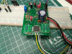
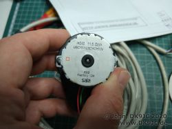
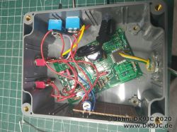
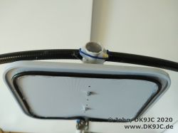
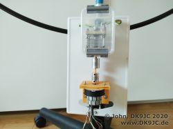
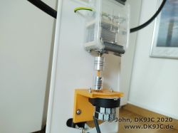
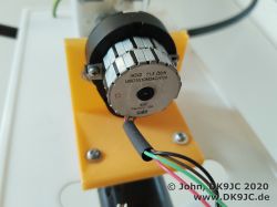
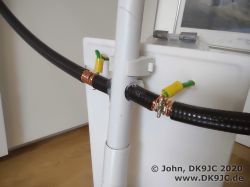
I added a stepper motor to my single-turn 1/2" Andrew heliax (around 11mm diameter) loop. The motor and the control board (based on a TMC236A) were bought on "Ham Radio" 2019 in Friedrichshafen from Dieter, DJ2EH. Stepper times can be varied from around 3-30ms. He also supported me very well with a minor issue I faced during the build.
With this antenna I worked more than 100 DXCC already from inside my apartement!
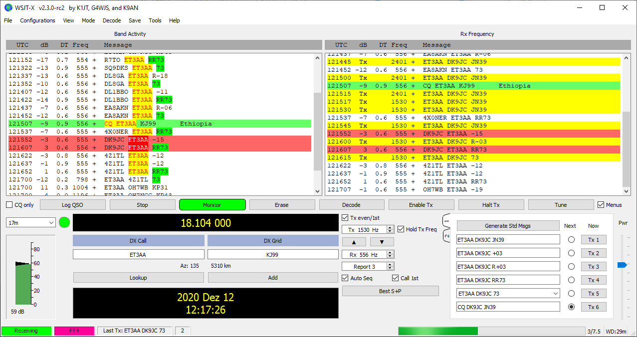
The last DX was ET3AA in Ethiopia on 17m FT8. "Only 5350 km (3300 miles), but that was an ATNO for me.
Update November / December 2020:
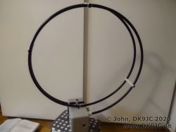
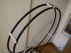
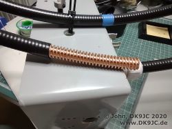
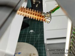
Wanted a stiff multi-turn loop so I made one with spare massive 1/2" Andrew heliax (around 11mm diameter) for 40m digimodes from home. It's made out of a single 4m / 13,12 ft piece of heliax. The circumference is 2 x 65 cm / 2 x 25 inch. Not many DX worked but almost all European countries. Will update this text soon, when I am finished with the project. Still some ongoing improvements.
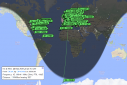
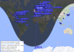
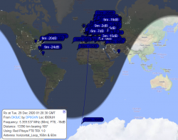
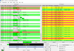
The last night I had 30m, 40m and 60m each running on CQ for about 1,5 hours. Screenshots in the gallery. The German Antarctic research station "DP0GVN" received my on every band. -11db on 30m, -14 db on 40m and -16db on 60m. With under 10W PEP this is way better than expected. 13.390 km / 8.320 miles. Of course they have extremely low noise levels, but I still find this impressive. I also added some plots from my VNA. After some problems with the size of the coupling loop I am now able to get a mostly resistive match.
Update 25.12.2020: - SOTA & portable magnetic loop antenna
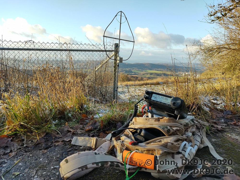
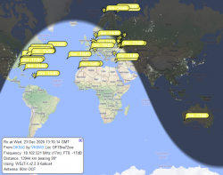
After years of using my homebrew magnetic loops as my main antennas from inside my apartement, it was time to make one for portable work while on SOTA or on travels. For /p and SOTA the antenna should at least cover 40m and 20m. They are most useful for portable activations as they are very reliable. In the end my /P magnetic loop covered 40m-10m (7090kHz - 29200 kHz). I already had all the experience and materials from previous builds at home, so after some hours the first indoor tests with FT8 took place. I did all FT8 tests with 10W for around 15 - 30 minutes per band. VK6WX heard me on 17m with -17 and I heard him -10. Not bad for an indoor antenna and 14.000km (8700 miles). I tried to call him for 20 minutes but then I had to leave. I am sure this will work, but he was busy answering a lot of callers. With some patience I later worked KP4JRS in Puerto Rico on 20m FT4. The first DX was worked with the new DIY portable mag loop. 7316km / 4540 miles.
After those very good and promising results from home I took the antenna out for a SSB SOTA-activation from Schaumberg DM/SR-012 / DLFF-0105.
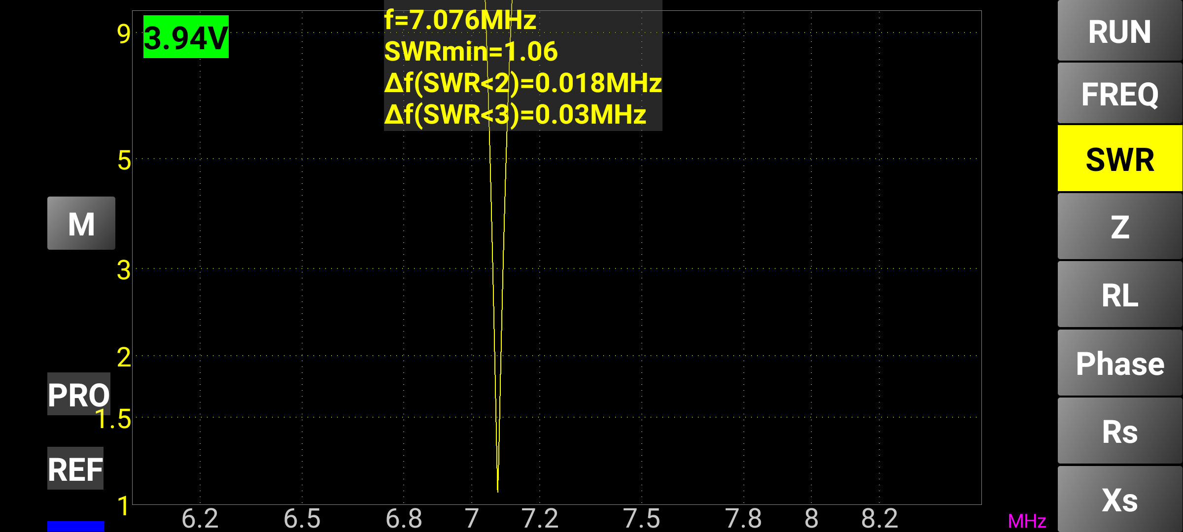
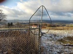
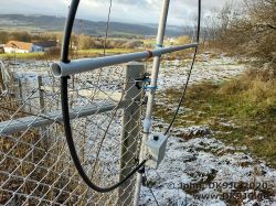
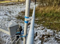
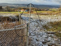
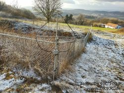
It worked very good on 40m after I adjusted the circular coupling loop to an oval shape. Quick SWR-check outside with the antenna mount to a metal fence:
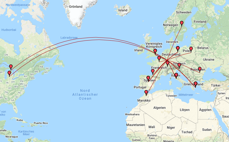
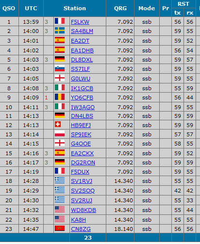
I tried all bands and they were perfectly tunable. On 40m I worked a lot of EU. 23 QSO into 13 DXCC. Best DX were WD8KDB & KA8H both in MI, USA on 20m and CN8ZG in Morocco on 17m.
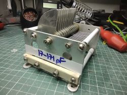
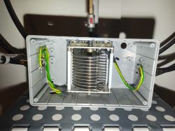
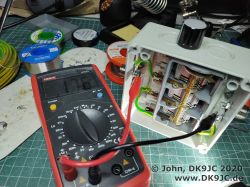
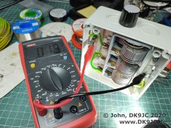
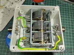
I used an old AM-radio air variable capacitor. I found it for a few bucks on one of the hamfests somewhere. I had 3 sections with 25-340 pF each. I left one unconnected and put the other two in series. The voltage rating was doubled, but the new capacitance was only 18-175 pF, which was still okay for 40-10m.
I also found some good info online about the principle that I use:
Multi-section: basically two (or more) variable capacitors that are ganged (mounted side-by-side), with a single conductive rotor shaft. Hence, the rotor vanes of all capacitor sections are electrically connected. The losses of the wiper contact can be eliminated by putting two capacitor sections in series: the rotor contact is not used, only the two stator contacts. This doubles the voltage rating, but at the same time halves the total capacitance. However, note that parasitic capacitance of the capacitor is not cut in half, so neither is the smallest achievable capacitance!
Source: Frank, N4SPP
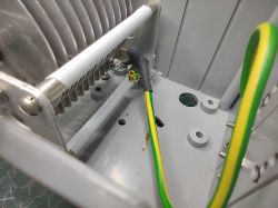
Additional note: The metal case is the connector between the two used capacitor sections, so no further connections are needed.
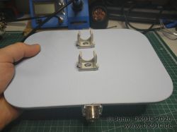
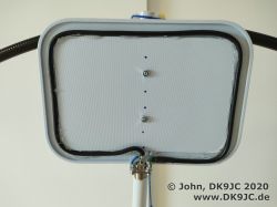
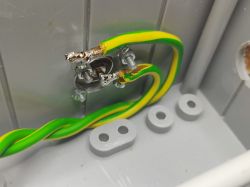
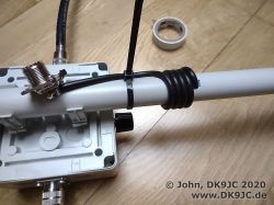
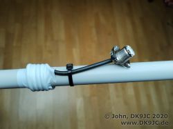
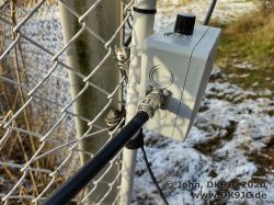
For the main (big) loop I used 295cm (116 inch) RG-214 (double-shielded RG-213) which I had already from previous builds. I used regular PL-connectors and sockets. Inside my plastic box, I have shorted the inner conductor with the outer braid with a solder bride on the back of the PL-socket. The smaller coupling loop is around 1/5th of the large loop. No big surprises here, all known from theory and widely available sources. While we talk about sources: This is by far the best online source for magnetic loop knowledge: nonstopsystems - Frank Dörenberg, N4SPP - I always recommend his website if anyone asks me about magnetic loop antennas. 95% of all you need to know covered on one single page. How great is this?
For my /p loop with around 1m diameter I calculated the efficiency. I used the magloop calculator software by Klaus, DG0KW. Also the help PDF file is very interesting and I recommend to read it. So here are the values:
| Band | Efficiency in % | Gain | Voltage (20W Pout) |
| 10m | 85% | -0,71dBd | 2.000V |
| 12m | 78% | -1,04dBd | 2.200V |
| 15m | 67% | -1,72dBd | 2.450V |
| 17m | 55% |
-2,63dBd |
2.570V |
| 20m | 33% | -4,84dBd | 2.566V |
| 30m | 13% | -8,9dBd | 2.233V |
| 40m | 3,8% | -14,21dBd | 1.733V |
| 60m | 1,4% | -18,58dBd | 1.400V |
| 80m | 0,3% | -25,1dBd | 900V |

ich baue gerade ebenfalls eine MagLoop. Zu Deiner habe ich mal eine Frage: Wie groß hast Du die Koppelschleife bemessen?
Gruß, Rico
sehr interessanter Artikel. Mich würde dabei aber noch mehr Details zu dem Koaxkabel Kondensator interessieren. Hängt das entsprechende Koax einfach runter? Ist es am Ende "offen"? Ich habe mal gerechnet, für 14,070 Mhz, wäre das ca 80cm (bei 3m Umfang des Strahlers). Da würde mich mal ein genaues Verdrahtungsschema, bzw weitere Aufnahmen von dem Koax Kondensator interessieren. BEsten Dank
73,
Max
Hallo Heinz,
ich habe den Beitrag angepasst und deine Fragen dort beantwortet.
Viele Grüße