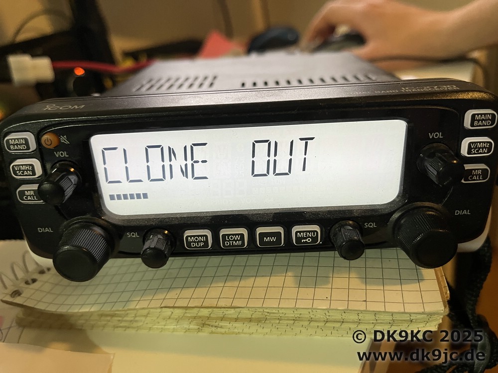
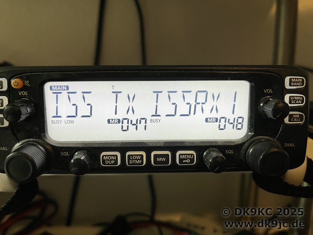
Some time ago I bought a Icom IC-2730E because it is one of the rigs with full-duplex and with its perfect filtering it can be used with great success on LEO FM Satellites.
Among other things, I used it in Iceland and activated some gridsquares there. Up to now, I have only ever used the IC-2730 manually in VFO mode, which somehow became very inconvenient. One big disadvantage was the cumbersome programming interface for programming the frequencies with the PC.
As I have always made the cables myself in the past, I thought that it should also work for this. As I have already received inquiries about X, I will briefly introduce the cable here.
First I looked in the original instructions to see what Icom recommends (or would like to sell as an accessory). In the manual I found “OPC-478UC” as the designation for accessories. Here in Germany, dealers offer the cable for 50 euros (50 US dollars). Of course this is too much.
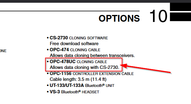
In the instructions and on the photos, it is also shown in two parts and is more complicated than it really is. In addition, the ICOM IC-2730 does not have its own connection for the cable. You have to use a 3.5mm stereo jack cable to connect it to the loudspeaker connection 2 (the one on the outside of the device).
A Google search “OPC-478UC” quickly showed me a circuit diagram which was apparently (thankfully) published by ICOM and drawn in 1997. This clearly shows the principle by which the interface works. If you still have a classic serial COM interface on your PC, you can build it according to this circuit diagram. OK1DX has also created a very nice documentation here.
I almost built it according to these designs, but I should have a USB cable. Since I have always built my other cables (also for C-IV on the ICOM IC910H, etc.) with a (probably) non-original FTDI from Aliexpress, I wanted to do the same this time. These chips with board and USB connector cost about 1 Euro / Dollar each, so I always have a stock.
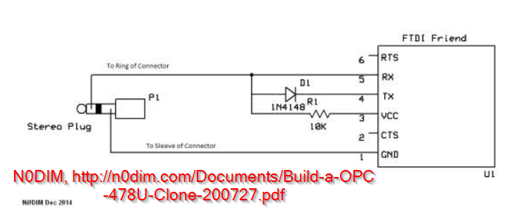
After searching for OPC-478UC and USB FTDI, I found a circuit diagram. A colleague (N0DIM) has already “adapted” the serial design (above) to USB and created a PDF. I link the PDF here. Here is the schematic:
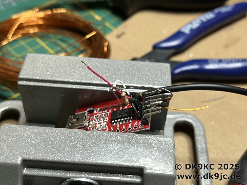
I like to use the mini USB FTDI chips with the breakout boards, i.e. the ones with the side contacts.
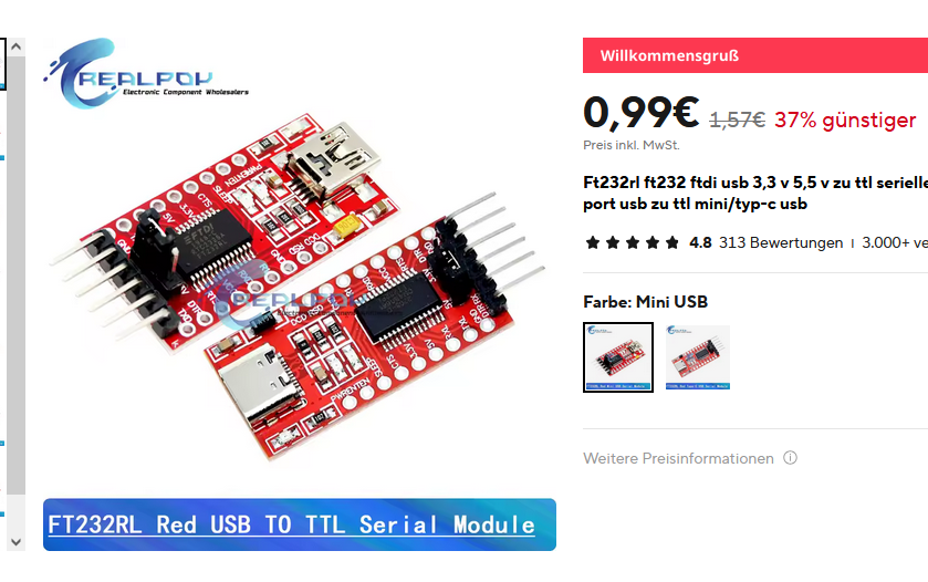
So it was easy to mount the 10k resistor directly on the board between RX and VCC. I soldered the diode to the plug contacts. For the 3.5mm jack you simply take what you have, possibly a short extension, and cut it into 2 halves. Then use a multimeter to measure which cable is which. The tip of the 3,5mm connector remains unconnected. The middle goes to RX, TX and VCC according to the circuit diagram and GND goes to GND.
The jumper for VCC I tried with 3.3V and it worked properly.
The cable probably also works with ICOM ID-5100, IC-T10, IC-R6, IC-F4029SDR, etc.
An alternative is the RT Systems USB-29A Programming Cable. In terms of price, this is more interesting for users from the USA. Unfortunately, this is also too expensive in the EU.
One more hint. I have an IC-2730E (Europe), it works without any problems with Chrip on the IC-2730A (America) version. There is also a free ICOM software (CS-2730) which I have not used yet.
